Model M150
FEATURES
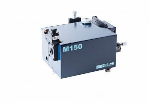
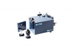
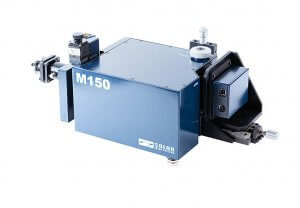
The M150 is our multi-purpose compact monochromator-spectrograph. The M150 is a low-cost short-focus instrument, flexible and multifunctional, featuring a unique combination of performance specifications and equipped with all the options essential for large-size spectrographs.
HIGH APERTURE RATIO (F=1:3.6)
LOW STRAY LIGHT
UP TO THREE DIFFRACTION GRATINGS MOUNTED ON THE AUTOMATED TURRET COVER A WIDE SPECTRAL RANGE WITH THE USE OF JUST ONE COMPACT DEVICE.
BOTH OUTPUT PORTS OF THE M150 HAVE FULLY FUNCTIONAL FLAT FIELD 30 X 10MM
HIGH DEGREE OF THE M150 AUTOMATION
THE IMAGING VERSION
THE SOLARLS.LAB SOFTWARE
DLL PROGRAM MODULES ANDOR LABVIEW DRIVERSBVIEW
DESCRIPTION
High aperture ratio (F=1:3.6) allows using the M150 for the widest range of routine purposes, including fluorescence, reflection and transmittance measurements in the wide spectral range from UV to IR, analysis of light sources, multi-channel spectroscopy and other applications.
Low stray light, due to high quality of the optical bench and careful engineering of the instrument housing, provides optimum signal-to-noise ratio.
Up to three diffraction gratings mounted on the automated turret cover a wide spectral range with the use of just one compact device.
Both output ports of the M150 have fully functional flat field 30 x 10mm and allow connecting either two exit slits or an exit slit and a multi-channel detector, or two detectors simultaneously, at your choice.
High degree of the M150 automation provides scanning and change of diffraction gratings, change of order-separating filters, adjustment of entrance slit width and automated background subtraction through shutter control.
Both exit slits of the M150 are equipped with precise mechanisms for slit focusing. Precise and easy detector focusing is provided by detector adapters
The IMAGING Version (Optional) ensures astigmatism compensation for the both output ports. This allows light delivery to the M150 with the set of optical fibers positioned along the entrance slit, as well as acquiring signal from array detectors not only in the Binning mode, but also in the Imaging mode.
The SolarLS.LAB software provides automated control over the M150 and its detector. It allows stitching spectra obtained by several diffraction grating scans in order to get a panoramic spectrum. Many possibilities of spectra processing and analysis are provided as well.
DLL program modules andor LabVIEW drivers are supplied at your request; they help to arrange the instrument handling within the general control program of your instrumentation system.
APPLICATIONS
Fluorescence and Raman Spectroscopy
As a Spectral Selection Device for Use with a Streak-Camera
Multichannel Spectroscopy
Measurements of Absorption, Reflection and Transmittance from UV to IR Range
CONFIGURATION
The M150 comprises one input port and two output ports. The input port may hold either a standard entrance slit, or a crossed entrance slit (optionally). The entrance slit is automated; slit opening width is software-controlled.
The standard optics comprises spherical and flat mirrors with Al+MgF2 coating optimised for high UV efficiency. Optionally the device may contain optics with Al+SiO2 or gold coating for high efficiency in the infrared spectral range.
The M150 includes a turret of three diffraction gratings. At your choice, the number of gratings can be reduced to one or two.
| MODIFICATION | COMPONENTS |
| M150-III | The standard optics and the turret with 3 diffraction gratings |
| M150-II | The standard optics and the turret with 2 diffraction gratings |
| M150-I | The standard optics and one diffraction grating |
| M150i-III | The Imaging optics (astigmatism compensator) and the turret with 3 diffraction gratings |
| M150i-II | The Imaging optics (astigmatism compensator) and the turret with 2 diffraction gratings |
| M150i-I | The Imaging optics (astigmatism compensator) and one diffraction grating |
The M150 output ports may hold either two exit slits, or one exit slit and a detector, or two detectors simultaneously.
Direct (axial) and lateral (radial) output ports operate alternately. Switching between the output ports is effected manually with the Port Switcher located at the upper cover of the instrument. The switcher moves the folding mirror, which directs light to the lateral (radial) output port. If the switcher is off, light goes to the direct (axial) output port.
The instrument is also available with one axial output port. If the radial output port is not used, it is plugged.
The M150 exit slit has 4 mounting holes M2.5 that allow you fixing your own detector to the slit housing, if necessary. Location of the mounting holes is shown in the figure below.
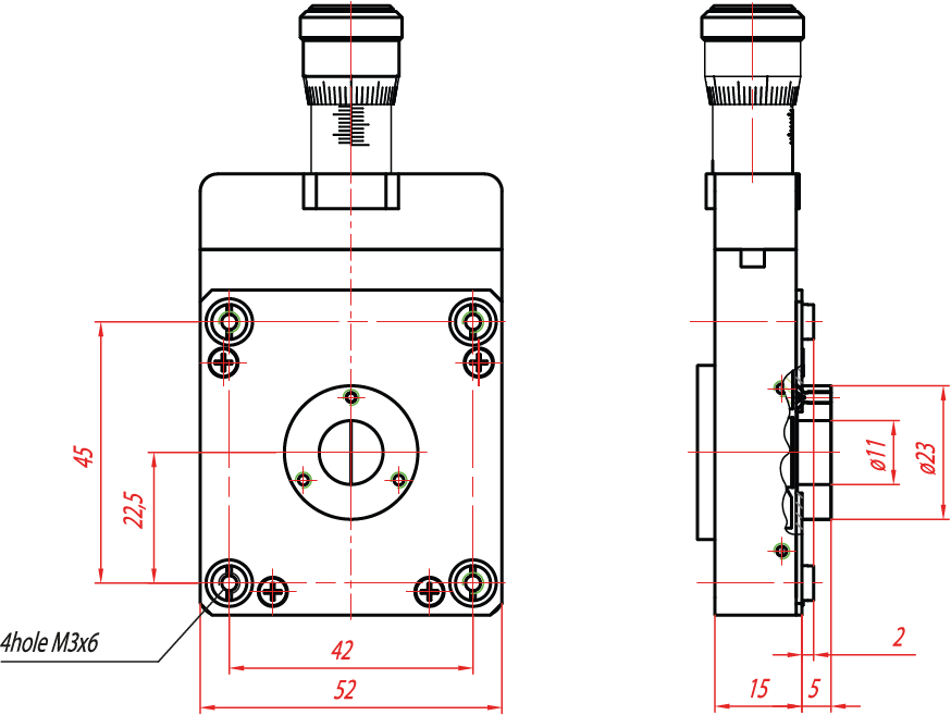
Note: To avoid a breakdown of the slit mechanism it is prohibited to fix any units weighing more than 1kg to the slit housing!
SPECIFICATIONS
| OPTICAL SCHEME | OPTIMIZED CZERNY-TURNER WITH ONE OPTICAL INPUT AND TWO OUTPUTS | |||||||||
| Spectral range | Typical 190 – 3600 nm (refer to the specification below); extended up to 15 µm (at your request) | |||||||||
| F/Number | 1 : 3.6 | |||||||||
| Focal length | 142 | |||||||||
| Flat field, mm | 30 x 10 | |||||||||
| Imaging | Option. Available on both output ports. | |||||||||
| Diffraction gratings | 40x40x10mm, turret with 3 gratings from the list below 1) | |||||||||
| — grooves/mm 1) | 1800 | 1200 | 900 | 600 | 600 | 400 | 300 | 200 | 100 | 100 |
| — blaze wavelength, nm | 270 | 400 | 600 | 750 | 100C0 | 800 | 1500 | 1500 | 2000 | 500 |
| — reciprocal linear dispersion (average), nm/mm | 3.2 | 4.9 | 6.4 | 9.8 | 9.4 | 15.2 | 20.1 | 30.4 | 63 | 68 |
| — spectral range 2), nm | 190-540 | 265-800 | 400-1200 | 500-1500 | 660-1800 | 530-1600 | 1000-3000 | 1000-3000 | 1330-4000 | 330-1000 |
| — multichannel array bandpass (average), nm | 813) | 1263) | 1653) | 2503) | 1204) | 1944) | 2574) | 3884) | 8004) | 8704) |
| — resolution (average), nm | 0.23) | 0.33) | 0.43) | 0.63) | 0.64) | 0.954) | 1.254) | 1.94) | 3.84) | 4.24) |
| 0.135) | 0.25) | 0.275) | ||||||||
| Entrance / Exit slit | Automatic / Manual adjustment | |||||||||
| — Slit width, mm | 0 — 3 | |||||||||
| — Slit height, mm | 10 | |||||||||
| — Parallelism, µm | +/- 1 | |||||||||
| — Micrometer reading accuracy, µm | +/- 1 | |||||||||
| — Step size, µm | 0.5 | |||||||||
| — Precision, µm | +/- 10 | |||||||||
| Filter wheel | Automatic switching | |||||||||
| — Max number of filters | 6 | |||||||||
| — Standard number of filters | 5 | |||||||||
| — Filter size, mm | 20 | |||||||||
| — Light aperture, mm | 18 | |||||||||
| Integrated shutter | Program-controlled, serves for measuring dark signal | |||||||||
| Computer interface | Full-Speed USB interface | |||||||||
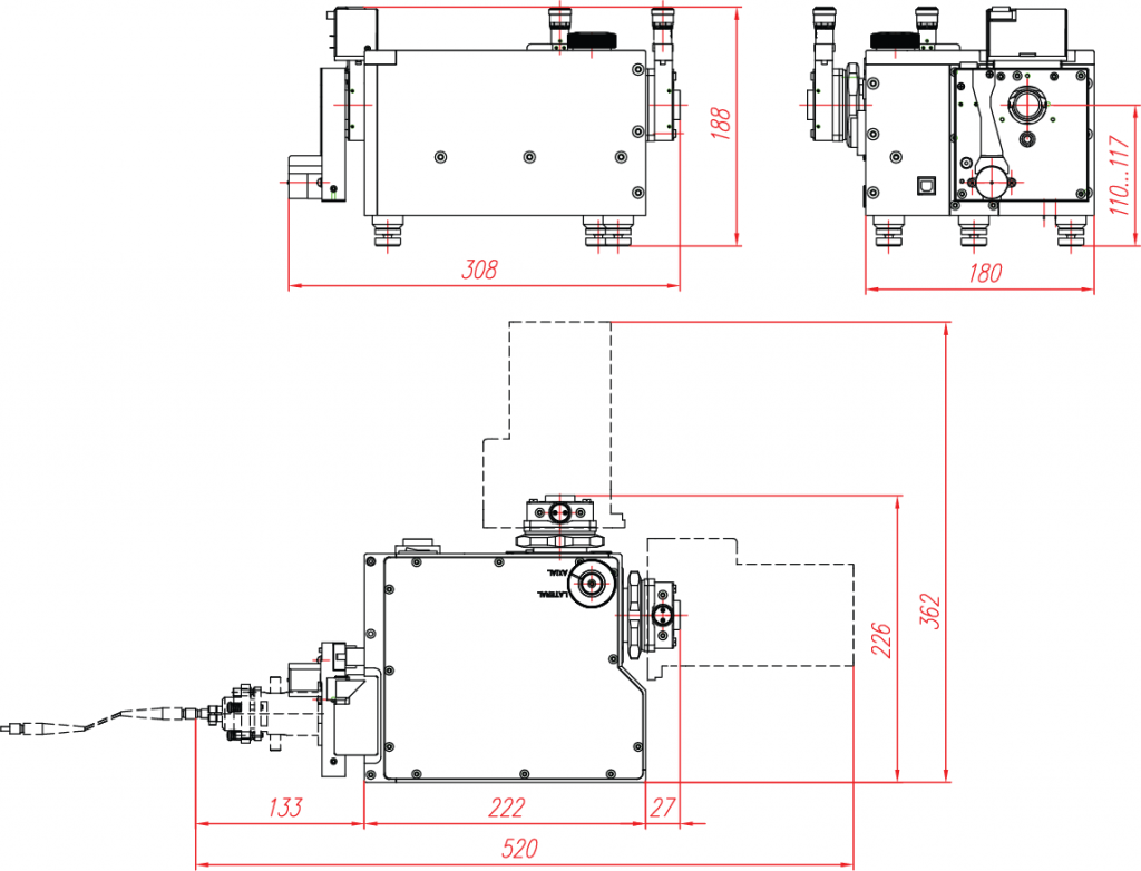
| Dimensions, weight | 308 х 226 х 188 mm, 8 kg | |||||||||
1) Upon your request, diffraction gratings with a different number of grooves per mm and blaze angle can be used.
2) Wavelength range with diffraction efficiency higher than 40%.
3) For the detector with 25µm pixel size and 25.6mm length of active area.
4) For the detector with 25µm pixel size and 12.8mm length of active area.
5) For the detector with 8µm pixel size and 29.1mm length of active area.
OPTIONS & ACCESSORIES
The M150 monochromator-spectrograph has a wide range of options and accessories that provide efficient light collection from the sample located at a finite distance and at infinity, delivering light to the monochromator with and without an optical fiber, effective aperture matching of the optical fiber and monochromator.
Order Separating Filters Wheels
Aperture Matching Adapters
Condensers for collecting light into the fiber
Condensers for collecting light into the monochromator
Crossed Entrance Slit (optionally installed instead of the Standard Entrance Slit)
Optical Fibers
Adapters for attaching CCD detectors
CCD detectors
Cassegrain lenses
All exit slits are equipped with precision focusing devices; and detector adapters allow easy detector focusing. The detector adapter of the long-focus M833 monochromator-spectrograph allows changing the slope of detector plane relative to the optical bench.
Cassegrain lenses allow collecting light from objects located at a distance of 3.5m to infinity.
Adapters PS-2 and PS-3 are designed for the collection of light from a closely located sample and its effective input into an optical fiber. PS-2 features high transmittance in the UV range, while PS-3 has the possibility of installing an edge filter.
Contact a SOLAR LS specialist to select the complete set of your monochromator-spectrograph that meets the requirements for your instrument complex in the best way.
MULTI-CHANNEL CCD DETECTORS
| MULTICHANNEL CCD DETECTORS BY ANDOR TECHNOLOGY TM | |
| iVac Series, Spectroscopic CCD | DR 324B-FI model, front-illuminated CCD sensor, UltraVacTM thermo-electric cooling down to -60°C, spectral range 400-1000nm, 1650*200pixels, pixel size 16*16µm, image area 26.4mm * 3.2mm, 16 bits digitisation |
| iDus Series, Spectroscopic CCD | DV 401A-BV model, back-illuminated CCD sensor, UltraVacTM thermo-electric cooling down to -70°C, spectral range 200-1100nm, 1024*127pixels, pixel size 26*26µm, image area 26.6mm * 3.6mm, 16 bits digitisation |
| DU 401A-BV model, back-illuminated CCD sensor, UltraVacTM thermo-electric cooling down to -100°C, spectral range 200-1100nm, 1024*127pixels, pixel size 26*26µm, image area 26.6mm * 3.6mm, 16 bits digitisation. | |
| Newton Series, EMCCD | DU970P-FI model (*), front-illuminated EMCCD sensor, UltraVacTM thermo-electric cooling down to -100°C, spectral range 400-1000nm, 1600*200pixels, pixel size 16*16µm, dual output amplifier, crop mode, Variable readout speed up to 3MHz, 16 bits digitisation. |
| DU970P-BV model (*), back-illuminated EMCCD sensor, UltraVacTM thermo-electric cooling down to -100°C, spectral range 200-1000nm, 1600*200pixels, pixel size 16*16µm, dual output amplifier, crop mode, Variable readout speed up to 3MHz, 16 bits digitisation | |
| iStar Series, Gated iCCD | DH320T-25U-03 model (*), Ultra Fast Gated Intensified CCD Camera, spectral range 200-900nm, 124*256 CCD 100% Fill Factor, 25mm tube, Gen2 Multialkali S20 Photocathode, P43 phosphor Multi-Mhz Readout Speeds, Integrated Digital Delay Generator, 3 ns Crop Mode sensor, Photocathode dry gas purge port, USB data interface. |
(*) other models are supplied upon request
| TWO-DIMENSIONAL HAMAMATSU ARRAYS FOR THE 200-1100NM RANGE | |
| UC-16H7306, Spectroscopic CCD | S7030-1006 sensor, non-cooled, spectral range 200-1100nm, 1024×64 pixels, pixel size 24×24µm, image area 24.6×1.4mm, 16 bit digitization |
| UC-16H7307, Spectroscopic CCD | S7030-1007 sensor, non-cooled, spectral range 200-1100nm, 1024×128 pixels, pixel size 24×24µm, image area 24.6×2.9mm, 16 bit digitization |
| UC-16H7316, Spectroscopic CCD | S7031-1006 back-illuminated sensor, TE cooling –10°C, spectral range 200-1100nm, 1024×64 pixels, pixel size 24×24µm, image area 24.6×1.4mm, 16 bit digitization |
| UC-16H7317, Spectroscopic CCD | S7031-1007 back-illuminated sensor, TE cooling –10°C, spectral range 200-1100nm, 1024×128 pixels, pixel size 24×24µm, image area 24.6×2.9mm, 16 bit digitization |
| UC-16H7318, Spectroscopic CCD | S7031-1008 back-illuminated sensor, TE cooling –10°C, spectral range 200-1100nm, 1024×256 pixels, pixel size 24×24 µm, image area 24.6 x 6.1mm, 16 bit digitization |
| U2C-16H10426, Spectroscopic CCD | S10420-1106-01 back-illuminated sensor, non-cooled, spectral range 200-1100nm, 2068х70 pixels, pixel size 14х14 µm, image area 28.672х0.896mm, 16 bit digitization |
| U2C-16H11516, Spectroscopic CCD | S11510-1106 back-illuminated sensor, non-cooled, spectral range 200-1100nm, 2068х70 pixels, pixel size 14х14 µm, image area 28,672х0,896mm, 16 bit digitization |
| U2C-16H11850, Spectroscopic CCD | S11850 back-illuminated sensor, TE cooling 5°С, , spectral range 200-1200nm, 2068х70 pixels, pixel size 14х14 µm, image area 28,672х0,896mm, 16 bit digitization |
| U2C-16H101409, Spectroscopic CCD | S10140-1109 back-illuminated sensor, non-cooled, , spectral range 200-1100nm, 2068х70 pixels, pixel size 14х14 µm, image area 28,672х0,896mm, 16 bit digitization |
| U2C-16H101419, Spectroscopic CCD | S10141-1109 back-illuminated sensor, TE cooling -10°C, , spectral range 200-1200nm, 2068х512 pixels, pixel size 12х12 µm, image area 24,576х6,072mm, 16 bit digitization |
| LINEAR INGAAS HAMAMATSU SENSORS FOR NIR-RANGE 900-1700NM (UP TO 2600NM) | |
| UC-16H904, InGaAs sensor | G9204-512D image sensor, spectral range 0.9-1.7µm, non-cooled, 512 pixels, pixel size 25×500µm, image area 12.8×0.5mm, 16 bit digitization |
| UC-16H912, InGaAs sensor | G9212-512S image sensor, InGaAs, spectral range 0.9-1.7µm, TE cooling –10°C, 512 pixels, pixel size 25×250µm, image area 12.8×0.25mm, 16 bit digitization |
| UC-16H914, InGaAs sensor | G9214-512S image sensor, InGaAs, spectral range 0.9-1.7µm, TE cooling –10°C, 512 pixels, pixel size 25×500µm, image area 12.8×0.5mm, 16 bit digitization |
| UC-16H908, InGaAs sensor | G9208-256W image sensor, InGaAs, spectral range 0.9-2.6µm, TE cooling –20°C, 256 pixels, pixel size 50×250µm, image area 12.8×0.25mm, 16 bit digitization |
| LINEAR NON-COOLED SENSORS FOR THE 200-1100NM RANGE | |
| UC-12T3 | TCD1304 image sensor, spectral range 190-1100nm, non-cooled, 3648 pixels, pixel width 8µm, image area 29.18×0.2mm, 14 bit digitization |
| UC-12T2 | TCD1205 image sensor, spectral range 200-1100nm, non-cooled, 2048 pixels, pixel width 14µm, image area 28.672×0.2mm,14 bit digitization |
| U2C-14H13496 | S13496 image sensor, spectral range 200-1000nm, non-cooled, 4096 pixels, pixel size 7 µm, 14 bit digitization |
| U2C-14H11639 | S11639-01 image sensor, spectral range 200-1000nm, non-cooled, 2048 pixels, pixel size 14 µm, 14 bit digitization |
OPTICAL BENCH FEATURES
The M150 is a short-focus monochromator combining compact size with extremely high aperture ratio (F=1:3.6).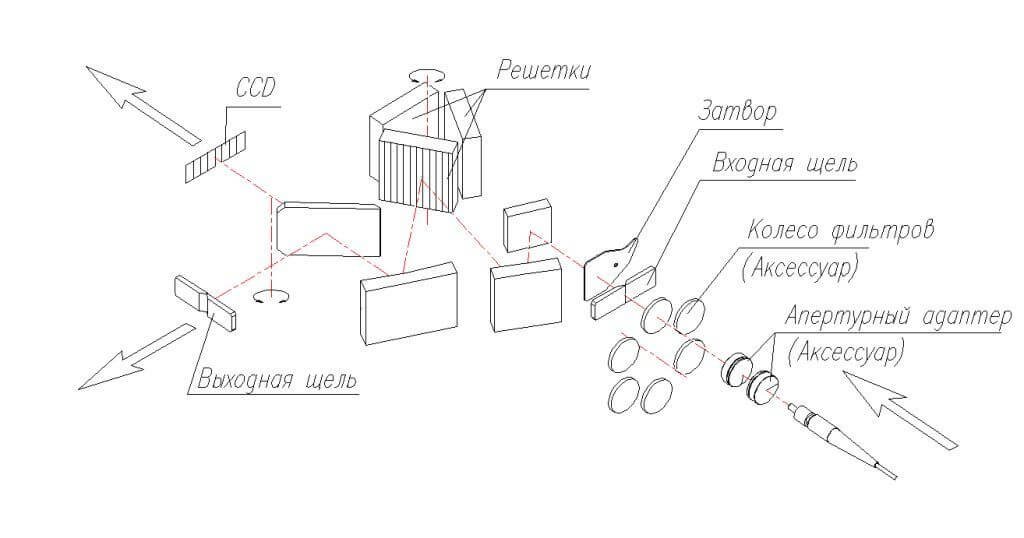
The main difficulty encountered at the development of the M150 optical bench was a necessity to ensure high optical quality within a miniature short-focus device with large-size optical elements and large angles at mirrors and gratings. This task was solved on the basis of the modified Czerny-Turner optical bench, where the entrance slit and exit slit (the centre of spectrum) are arranged asymmetrically relative to the diffraction grating. The unique combination of high aperture ratio and outstanding line quality was implemented by careful optimisation of focal distances for collimator and camera mirrors, and of angular relationship at the optical elements. The M150i (Imaging) modification contains a specifically designed astigmatism compensator, which is installed into the M150 optical bench instead of the first folding mirror and ensures absence of astigmatism at both output ports of the instrument.
Another difficulty encountered at the stage of the M150 development and brilliantly solved by our designers, was a necessity to place maximum functionality and convenience of use in a miniature design.
The result is the M150 – a multifunctional short-focus monochromator-spectrograph featuring the unique combination of performance specifications and equipped with all the options common for large-size monochromators and spectrographs. The M150 comprises two output ports and provides the possibility of full-featured operation with both of them. Either port may hold an entrance slit with a smooth-focusing mechanism or a CCD-detector with an adapter which provides its easy alignment by focus.
The large 30mmx10mm flat filed of the M150 spectrograph ensures a large multichannel array bandpass and a possibility of high-quality software sewing of spectra obtained in several scans.
The M150 is also compatible with all the accessories by SOLAR LS: a wheel of order-separating filters, adapters for matching apertures of the fiber and monochromator, adapters for collecting light into the optical fiber, etc.
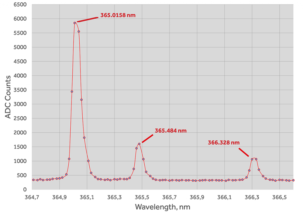
Mercury lamp lines 365.0158 nm, 365.484 nm, 366.328 nm registered with M150 on the diffraction grating 1800 gr/mm demonstrate high optical quality of the instrument.
ASTIGMATISM COMPENSATION
Generally, astigmatism is common to all spectral instruments; this is a phenomenon when the point on the entrance slit is displayed in the image plane as a vertical segment. The M150 astigmatic segment is 8mm in the center of the flat field, and 6.5 mm and 10 mm at the edges of the field respectively. Astigmatism does not usually impair the instrument resolution, but, depending on the height of the detector used, can affect the overall sensitivity of the system.
Astigmatism correction is imperative in the multichannel spectroscopy, in case you need to adequately convey the light distribution along the slit, as well as for the use of the spectrograph with 2D detectors in the Imaging mode.
The M150i astigmatism compensator is a cylindrical mirror which is installed after the entrance slit instead of a flat folding mirror. Astigmatism is compensated at the both output ports. Introducing the astigmatism compensator in the optical scheme allows correcting astigmatism in the exit slit plane to the value of about 50µm. This fact must be considered when calculating the expected optical resolution of the M150 with a specific grating. Astigmatism compensation also affects the M150 vertical magnification:
| M150 MAGNIFICATION | HORIZONTAL MAGNIFICATION | VERTICAL MAGNIFICATION |
| without astigmatism compensation | 1.15 | 1.0 |
| with astigmatism compensation | 1.15 | 1.35 |
SOLARLS的所有資訊來自SOLARLS網頁,所有版權歸SOLARLS,繁體字版權屬安均科技。