Model M266
FEATURES
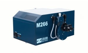
Monochromator M266 is our general-purpose high-aperture instrument with high line quality and low stray light performance, featuring 284mm focus and 30x10mm flat field.
HIGH APERTURE RATIO (F=1:3.8)
TWO OUTPUT PORTS
THE M266I VERSION (IMAGING)
M266 IS COMPLETELY AUTOMATED
DESCRIPTION
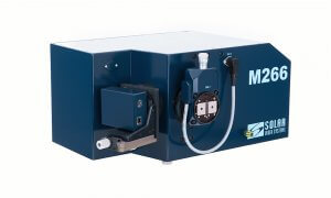
High aperture ratio (F=1:3.8), low stray light and perfect line quality enable successful use of the M266 in a wide range of applications.
Two output ports allow connecting to the M266 either two exit slits, exit slit/detector or two detectors concurrently.
The M266i version (Imaging) features an astigmatism compensator for both output ports, thus promoting the use of the M266 with matrix detectors in the multi-channel spectroscopy, not only in the binning mode, but also in the 2D-image mode.
M266 is completely automated. Spectrum scanning along wavelengths, change of gratings and order separating filters, adjustment of slit width and selection of an output port are performed automatically, guided by the intelligent and easy-to-use software.
An automatic shutter provides for automatic background (dark current) subtraction, along with detector protection against excessive illumination from the light source.
The SolarLS.LAB software provides automated control over the monochrometer M266 and its detectors. It allows stitching spectra obtained by several diffraction grating scans in order to get a panoramic spectrum. Many possibilities of spectra processing and analysis are provided as well.
At your request, DLL andor LabView drivers are supplied with the M266 for controlling the instrument via the customised software or LabView.
APPLICATIONS
Emission, Fluorescence and Raman Spectroscopy
Multi-Channel Spectroscopy
Absorption, Reflection and Transmission
Measurements
Analytical Tasks from UV to IR
INSTRUMENT CONFIGURATION
The M266 comprises one input port and two output ports. The input port may hold either a standard entrance slit, or a crossed entrance slit (optionally). All the spectral slits are automated; their width is adjusted by the instrument software. The slit design also contains a microscrew, which provides the possibility to manually adjust the opening width of the knives.
Depending on modification, the M266 may contain either a turret with four diffraction gratings, or one grating in the holder.
| MODIFICATION | COMPONENTS |
| M266-IV | The standard optics and the turret with 4 diffraction gratings |
| M266i-IV | The Imaging optics (astigmatism compensator) and the turret with 4 diffraction gratings |
| M266-I | The standard optics and one diffraction grating |
| M266i-I | The Imaging optics (astigmatism compensator) and one diffraction grating |
The standard optics comprises spherical and flat mirrors with Al+MgF2 coating optimised for high UV efficiency. Optionally the device may contain optics with Al+SiO2 or gold coating for high efficiency in the infrared spectral range.
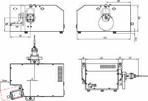
The M266 output ports may hold either two exit slits, or one exit slit and detector, or two detectors concurrently.
Direct (axial) and lateral (radial) output ports operate alternately. Switching between the output ports is effected by the software with the use of the swinging mirror, which in its operating position directs light to the lateral (radial) output port. The instrument is also available with one output (axial) port. If the radial output port is not used, it is plugged.
The M266 exit slit has 4 mounting holes M2.5 that allow you fixing your own detector to the slit housing, if necessary. Location of the mounting holes is shown in the figure below.
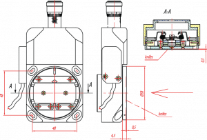
Note: To avoid a breakdown of the slit mechanism it is prohibited to fix any units weighing more than 1kg to the slit housing.
SPECIFICATIONS
| OPTICAL BENCH | OPTIMIZED CZERNY-TURNER WITH ONE INPUT AND TWO OUTPUTS | |||
Spectral range
| — typical 180 – 3600 nm (see the specifications below), — extended up to 40 µm (upon request) | |||
| F/Number | 1 : 3.8 | |||
| Focal length, mm | 284 | |||
| Flat field, mm | 30 x 10 | |||
| Imaging | Option. Available for the both output ports simultaneously. | |||
| Gratings | 50x50x10mm, one grating or a turret with 4 gratings from the list below1). | |||
| — grooves/mm1) | 1800 | 1200 | 600 | 300 |
| — reciprocal linear dispersion (average), nm/mm 2) | 2.12 | 3.18 | 6.37 | 12.64 |
| — blazing wavelength, nm | 270 | 400 | 750 | 2000 |
| — spectral range, nm 3) | 180-600 | 265-900 | 500-1500 | 1330-3600 |
| — multichannel array bandpass, (average), nm | 51 4) | 76 4) | 150 4) | 160 5) |
| — resolution (average), nm | <0.154) | <0.224) | <0.45 4) 0.26) | <0.945) |
| 0.076) | 0.16) | |||
| — Wavelength accuracy, nm | ±0.067 | ±0.1 | ±0.2 | ±0.4 |
| — Wavelength reproducibility, nm | ±0.017 | ±0.025 | ±0.05 | ±0.1 |
| — Step of grating rotation, nm | 0.009 | 0.013 | 0.026 | 0.05 |
| — Scanning speed, nm/s | 16.7 | 25 | 50 | 100 |
| Entrance/exit slits | Automatic and manual adjustment | |||
| — Slit width, mm | 0 — 2 | |||
| — Slit height, mm | 12 | |||
| — Parallelism, µm | +/- 1 | |||
| — Micrometer reading accuracy, µm | +/- 1 | |||
| — Step size, µm | 0.5 | |||
| — Precision, µm | +/- 10 | |||
| Filter wheel | Automatic switching | |||
| — Max number of filters | 8 | |||
| — Standard number of filters | 5 | |||
| — Filter size, mm | 20 | |||
| — Light aperture, mm | 18 | |||
| Integrated shutter | Computer controlled, serves for dark signal measuring | |||
| Computer interface | High-Speed USB | |||
| Dimensions and Weight | 252 х 213 mm, 23.5 kg | |||
1) Upon your request, diffraction gratings with another grooves quantity/blazing angle can be used.
2) Reciprocal linear dispersion is indicated for blazing wavelength
3) Wavelength range for which diffraction efficiency exceeds 40%
4) For detector with 24 µm pixel size and 5 mm active area
5) For detector with 25 µm pixel size and 8 mm active area
6) For detector with 8 µm pixel size and 1 mm active area
OPTIONS & ACCESSORIES
The M266 monochromator-spectrograph has a wide range of options and accessories that provide efficient light collection from the sample located at a finite distance and at infinity, delivering light to the monochromator with and without an optical fiber, effective aperture matching of the optical fiber and monochromator.
Order Separating Filters Wheels
Aperture Matching Adapters
Condensers for collecting light into the fiber
Condensers for collecting light into the monochromator
Crossed Entrance Slit (optionally installed instead of the Standard Entrance Slit)
Optical Fibers
Adapters for attaching CCD detectors
CCD detectors
Cassegrain lenses
All exit slits are equipped with precision focusing devices; and detector adapters allow easy detector focusing. The detector adapter of the long-focus M833 monochromator-spectrograph allows changing the slope of detector plane relative to the optical bench.
Cassegrain lenses allow collecting light from objects located at a distance of 3.5m to infinity.
Adapters PS-2 and PS-3 are designed for the collection of light from a closely located sample and its effective input into an optical fiber. PS-2 features high transmittance in the UV range, while PS-3 has the possibility of installing an edge filter.
Contact a SOLAR LS specialist to select the complete set of your monochromator-spectrograph that meets the requirements for your instrument complex in the best way.
MULTI-CHANNEL CCD DETECTORS
| MULTICHANNEL CCD DETECTORS BY ANDOR TECHNOLOGY TM | |
| iVac Series, Spectroscopic CCD | DR 324B-FI model, front-illuminated CCD sensor, UltraVacTM thermo-electric cooling down to -60°C, spectral range 400-1000nm, 1650*200pixels, pixel size 16*16µm, image area 26.4mm * 3.2mm, 16 bits digitisation |
| iDus Series, Spectroscopic CCD | DV 401A-BV model, back-illuminated CCD sensor, UltraVacTM thermo-electric cooling down to -70°C, spectral range 200-1100nm, 1024*127pixels, pixel size 26*26µm, image area 26.6mm * 3.6mm, 16 bits digitisation |
| DU 401A-BV model, back-illuminated CCD sensor, UltraVacTM thermo-electric cooling down to -100°C, spectral range 200-1100nm, 1024*127pixels, pixel size 26*26µm, image area 26.6mm * 3.6mm, 16 bits digitisation. | |
| Newton Series, EMCCD | DU970P-FI model (*), front-illuminated EMCCD sensor, UltraVacTM thermo-electric cooling down to -100°C, spectral range 400-1000nm, 1600*200pixels, pixel size 16*16µm, dual output amplifier, crop mode, Variable readout speed up to 3MHz, 16 bits digitisation. |
| DU970P-BV model (*), back-illuminated EMCCD sensor, UltraVacTM thermo-electric cooling down to -100°C, spectral range 200-1000nm, 1600*200pixels, pixel size 16*16µm, dual output amplifier, crop mode, Variable readout speed up to 3MHz, 16 bits digitisation | |
| iStar Series, Gated iCCD | DH320T-25U-03 model (*), Ultra Fast Gated Intensified CCD Camera, spectral range 200-900nm, 124*256 CCD 100% Fill Factor, 25mm tube, Gen2 Multialkali S20 Photocathode, P43 phosphor Multi-Mhz Readout Speeds, Integrated Digital Delay Generator, 3 ns Crop Mode sensor, Photocathode dry gas purge port, USB data interface. |
(*) other models are supplied upon request
| TWO-DIMENSIONAL HAMAMATSU ARRAYS FOR THE 200-1100NM RANGE | |
| UC-16H7306, Spectroscopic CCD | S7030-1006 sensor, non-cooled, spectral range 200-1100nm, 1024×64 pixels, pixel size 24×24µm, image area 24.6×1.4mm, 16 bit digitization |
| UC-16H7307, Spectroscopic CCD | S7030-1007 sensor, non-cooled, spectral range 200-1100nm, 1024×128 pixels, pixel size 24×24µm, image area 24.6×2.9mm, 16 bit digitization |
| UC-16H7316, Spectroscopic CCD | S7031-1006 back-illuminated sensor, TE cooling –10°C, spectral range 200-1100nm, 1024×64 pixels, pixel size 24×24µm, image area 24.6×1.4mm, 16 bit digitization |
| UC-16H7317, Spectroscopic CCD | S7031-1007 back-illuminated sensor, TE cooling –10°C, spectral range 200-1100nm, 1024×128 pixels, pixel size 24×24µm, image area 24.6×2.9mm, 16 bit digitization |
| UC-16H7318, Spectroscopic CCD | S7031-1008 back-illuminated sensor, TE cooling –10°C, spectral range 200-1100nm, 1024×256 pixels, pixel size 24×24 µm, image area 24.6 x 6.1mm, 16 bit digitization |
| U2C-16H10426, Spectroscopic CCD | S10420-1106-01 back-illuminated sensor, non-cooled, spectral range 200-1100nm, 2068х70 pixels, pixel size 14х14 µm, image area 28.672х0.896mm, 16 bit digitization |
| U2C-16H11516, Spectroscopic CCD | S11510-1106 back-illuminated sensor, non-cooled, spectral range 200-1100nm, 2068х70 pixels, pixel size 14х14 µm, image area 28,672х0,896mm, 16 bit digitization |
| U2C-16H11850, Spectroscopic CCD | S11850 back-illuminated sensor, TE cooling 5°С, , spectral range 200-1200nm, 2068х70 pixels, pixel size 14х14 µm, image area 28,672х0,896mm, 16 bit digitization |
| U2C-16H101409, Spectroscopic CCD | S10140-1109 back-illuminated sensor, non-cooled, , spectral range 200-1100nm, 2068х70 pixels, pixel size 14х14 µm, image area 28,672х0,896mm, 16 bit digitization |
| U2C-16H101419, Spectroscopic CCD | S10141-1109 back-illuminated sensor, TE cooling -10°C, , spectral range 200-1200nm, 2068х512 pixels, pixel size 12х12 µm, image area 24,576х6,072mm, 16 bit digitization |
| LINEAR INGAAS HAMAMATSU SENSORS FOR NIR-RANGE 900-1700NM (UP TO 2600NM) | |
| UC-16H904, InGaAs sensor | G9204-512D image sensor, spectral range 0.9-1.7µm, non-cooled, 512 pixels, pixel size 25×500µm, image area 12.8×0.5mm, 16 bit digitization |
| UC-16H912, InGaAs sensor | G9212-512S image sensor, InGaAs, spectral range 0.9-1.7µm, TE cooling –10°C, 512 pixels, pixel size 25×250µm, image area 12.8×0.25mm, 16 bit digitization |
| UC-16H914, InGaAs sensor | G9214-512S image sensor, InGaAs, spectral range 0.9-1.7µm, TE cooling –10°C, 512 pixels, pixel size 25×500µm, image area 12.8×0.5mm, 16 bit digitization |
| UC-16H908, InGaAs sensor | G9208-256W image sensor, InGaAs, spectral range 0.9-2.6µm, TE cooling –2C0°C, 256 pixels, pixel size 50×250µm, image area 12.8×0.25mm, 16 bit digitization |
| LINEAR NON-COOLED SENSORS FOR THE 200-1100NM RANGE | |
| UC-12T3 | TCD1304 image sensor, spectral range 190-1100nm, non-cooled, 3648 pixels, pixel width 8µm, image area 29.18×0.2mm, 14 bit digitization |
| UC-12T2 | TCD1205 image sensor, spectral range 200-1100nm, non-cooled, 2048 pixels, pixel width 14µm, image area 28.672×0.2mm,14 bit digitization |
| U2C-14H13496 | S13496 image sensor, spectral range 200-1000nm, non-cooled, 4096 pixels, pixel size 7 µm, 14 bit digitization |
| U2C-14H11639 | S11639-01 image sensor, spectral range 200-1000nm, non-cooled, 2048 pixels, pixel size 14 µm, 14 bit digitization |
OPTICAL BENCH FEATURES
The M266 monochromator-spectrograph is built on a modified Czerny-Turner bench, in which the entrance slit and the exit slit (the center of the spectrum) are arranged asymmetrically with respect to the diffraction grating. While developing an optical bench, this arrangement of optical components allows to considerably compensate aberrations inherent to spectral instruments with spherical mirrors, and to obtain the best spectral resolution.
In contrast to the broad range of monochromators, whose mechanisms of scanning and changing of diffraction gratings are combined, the M266 uses separate control for scanning and changing of gratings. As a result, an axis of grating rotation is the axis passing through the center of the grating. This design feature, together with the optimisation of linear and angular characteristics of the optical system, has allowed to completely eliminate beam re-reflections on optical elements, to provide extremely low stray light and create a perfect flat field for a multi-element detector.
The flat field, in its turn, enables high-quality program sewing of spectra obtained with the multi-element detector by means of several scans.
Astigmatism compensation (Imaging option)
The astigmatism compensator is a cylindrical mirror which is installed after the entrance slit instead of a flat rotating mirror and provides astigmatism compensation for both output ports (the Imaging version).
Astigmatism is common to all spectral instruments; this is a phenomenon when the point on the entrance slit is displayed in the image plane as a vertical segment. The M266 astigmatic segment is 2.4mm in the center of its output flat field, and respectively 2.1mm and 2.8mm at the edges of the field. Astigmatism does not usually impair resolution of the instrument, but, depending on the height of the detector used, can affect the overall sensitivity of the system.
Astigmatism correction is imperative in a multichannel spectroscopy, in case you need to adequately transfer the light distribution along the slit, as well as for the use of spectrographs with two-dimensional detectors in the Imaging mode.
Introducing the astigmatism compensator in the M266 optical scheme allows correcting astigmatism in the exit slit plane to the value of about 50 micrometers. This fact must be considered when estimating the expected optical resolution of an instrument with a specific grating. Astigmatism compensation also affects the vertical magnification of the spectrograph:
| M266 MAGNIFICATION | HORIZONTAL MAGNIFICATION | VERTICAL MAGNIFICATION |
| without astigmatism compensation (Standard mode) | 1.19 | 1.32 |
| with astigmatism compensation (Imaging mode) | 1.19 | 1.55 |
SPECTRA ACQUIRED WITH THE M266
Singlet oxygen spectra*
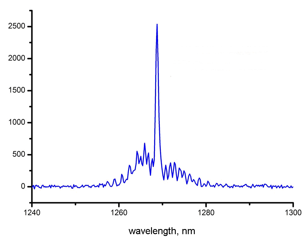
Emission spectrum of singlet oxygen in the 1268nm band in the supersonic flow. The M266 with the 400 lines/mm grating and the multi-channel InGaAs detector G9212-512S, entrance slit width 50µm
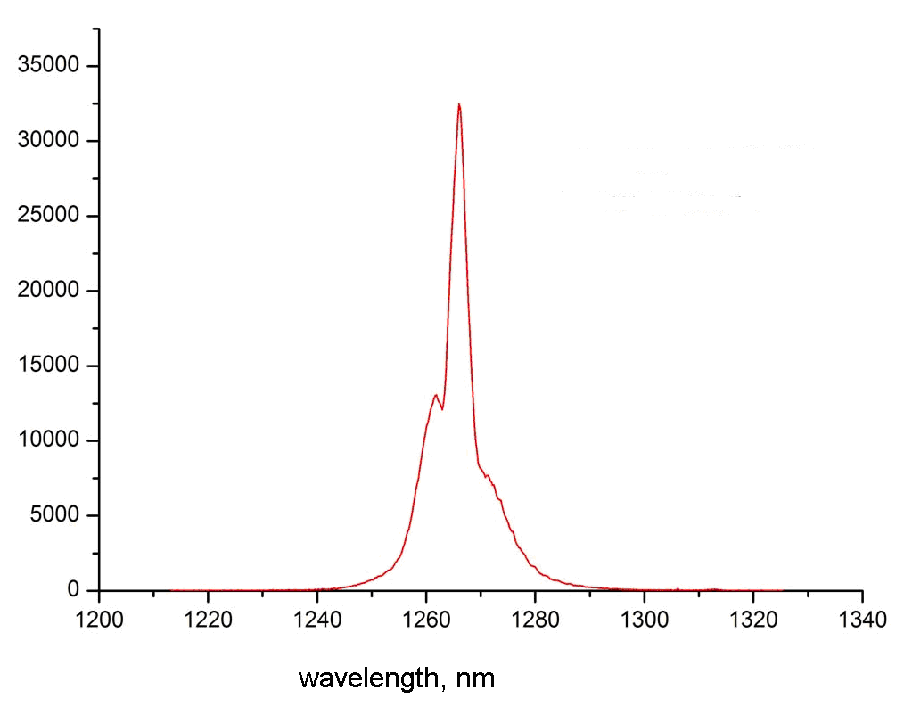
Emission spectrum of singlet oxygen at the gas generator output. The M266 with the 400 lines/mm grating and the multi-channel InGaAs detector G9212-512S, entrance slit width 400µm
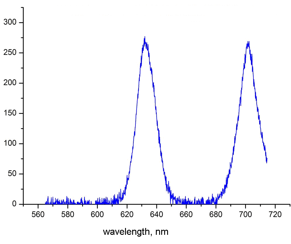
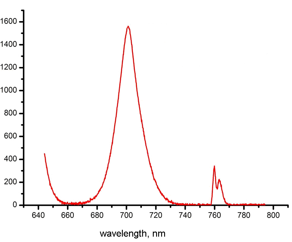
Oxygen emission spectrum in the bands 634nm and 703nm, arising from the collision of two singlet-oxygen molecules with their transition to the ground state, one molecule becoming vibrationally excited. The M266 with the 600 lines/mm grating and multi-channel InGaAs detector G9212-512S, entrance slit width 50 µm
The peak on the left is the spectrum arising from collision of two singlet-oxygen molecules with their transition to the ground state. The right spectrum in the 763nm band is emission of oxygen in the second electronically excited state
* Courtesy of Lebedev Physical Institute of the Academy of Sciences, Samara Branch, Samara, Russia.
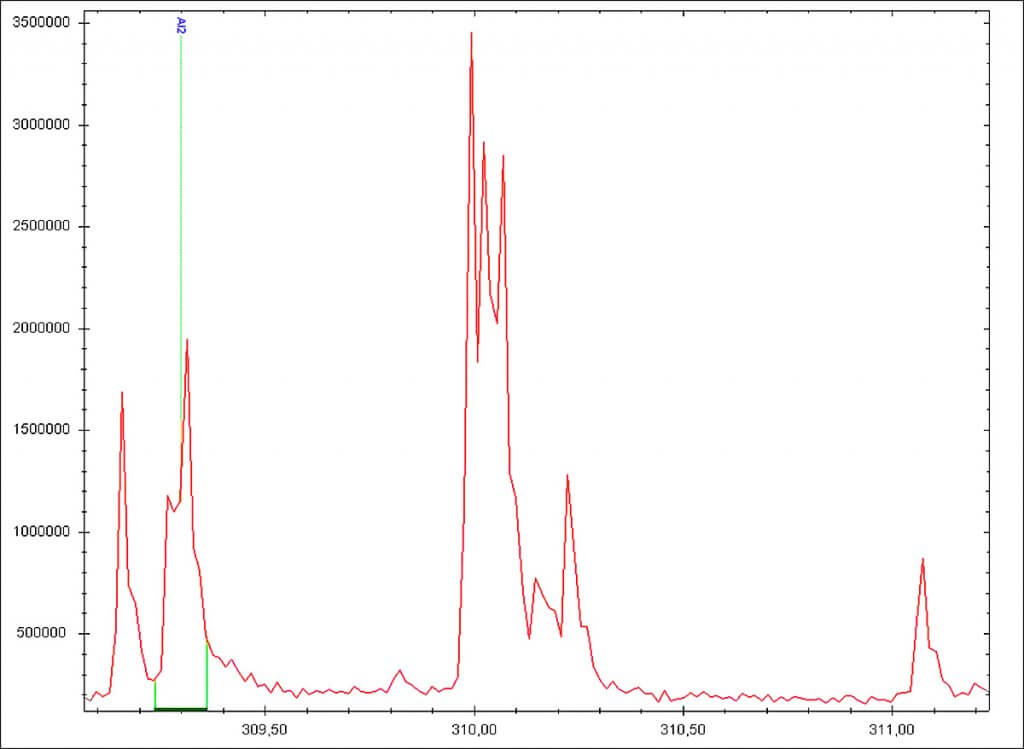
Emission spectra. Quadruplet Fe at 310nm
Fe quadruplet, spectral lines 309.9897nm, 309.9971nm, 310.0304nm and 310.0666nm. The spectrum was acquired with spark excitation using the M266 with 1800 lines/mm grating. The possibility of resolving at least 3 peaks demonstrates high optical quality of the instrument
SOLARLS的所有資訊來自SOLARLS網頁,所有版權歸SOLARLS,繁體字版權屬安均科技。
